INTRO
The attachment of the hips and belly rod was shown in the previous page. This page shows the attachment of the belly space frame parts #23 to #32.
These are located approximately where the arrows are indicating below.

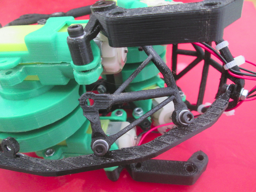
When completed it will look like this:

PARTS
List of components presented in this page:
- Rear corner brace, left (#23)
- Rear corner brace, right (#24)
- Small belly brace 1, left (#25)
- Small belly brace 1, right (#26)
- Large belly brace 1, left (#27)
- Large belly brace 1, right (#28)
- Small belly brace 2, left (#29)
- Small belly brace 2, right (#30)
- Large belly brace 2, left (#31)
- Large belly brace 2, right (#32)
- M3 socket screws, 10mm (x4)
- M3 socket screws, 6mm (x12)
- M3 nuts (x14)
- M3 washers (x16)
These are shown below. As this is getting more complicated, the new plastic parts have been coloured light blue.


As you can see there are 10 new parts to add.
And with the fasteners added:


Exploded views:


Images of the individual parts are provided below as they are used to make the assembly.
ASSEMBLY
It starts with the rear corner braces.


The rear corner brace, left is attached as shown below (yellow arrow).

This involves two M3 x 10mm socket screws (red arrows below) and two M3 x 6mm socket screws (yellow arrows) plus associated nuts and washers (generally all screws and nuts have washers unless embedded in a recess).

Nb: some nuts may already be in place in a recess from a previous page.
Also note, some other parts may have other parts fastened by the same screw and nut.
Next is the right rear corner brace (#24) which is a mirror image of the left side one.


As you can see in the CAD image above, the top lug of the rear corner braces has been trimmed to make it fit.
Once done it should look like this:

Next is to attach the small belly brace 1, left (#25).


The left and right versions (25, 26) are pretty much the same. they are technically mirror versions of each other so are treated as distinct. Anyway the attachment of each is the same, as shown below.
Part 25 above joins the rear corner brace, left (yellow arrow below, 24) to the left hip and to the lower crank assembly, left side motor holders (orange arrow) as shown below:

As you can see the motor / hip M3 screw, washer and nut should already be in place. An M3 x 10mm socket screw and washer are needed (the nut on the other side is captive, in a recess as shown further above).

Do the same on the right side with parts 24 & 26.
Next to add on the left side of the assembly are the large belly brace 1, left (27) and the small belly brace 2, left (29), shown below:


Part #29 needs to have a captive M3 nut inserted.
These are shown in the CAD image below.

The yellow arrow is the large belly brace1, left (27) and orange arrow points at the small belly brace 2, left (29).
Note that the right hand lug of part 27 is sandwiched between the lugs of the other two parts (green arrow below).


An M3 x 10mm socket screw is used at the orange arrow above and M3 x 6mm at the yellow arrow above.
Parts 28 & 30 are mirror versions of the two above and should be attached on the right hand side in the same way.

The above image shows parts 27, 28, 29 & 30 attached.
The last two components of the belly space frame are : the large belly brace 2, left (31, red arrow below); & the large belly brace 2, right (32, orange arrow below).


The top left and top right screws, washers and nuts will already be in place. A single M3 socket screw x 6mm plus washer is needed (bottom left). This is the ‘large belly brace 2, left’. Do similarly for the right side one (32).
The next page presents parts 33 to 40 which are the ‘shoulders’, ‘breast bone’ and associated components.