INTRO
The assembly of the Techno-Saurus was completed on the previous page (>>> Page 12). This page shows how to assemble the controller and the switches.
The design is very simple: when the trigger is squeezed it closes a micro switch to make the head and neck lunge and the jaws bite (and retract). The two slider switches allow for simple skid-steering of the claws.
Here is the CAD model of the controller assembly (nb wires not shown):

The assembled and fully wired up controller will look like this:

So, the two slider switches control the movements of the device (skid-steering) and the trigger causes the head, neck to move and the jaws to open and close.
PARTS
List of components presented in this page:
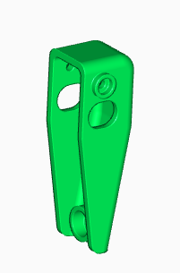
- Controller upper section (#70)
- Controller handle (#71)
- Controller trigger (#72)
- Compression spring: 20mm long, 5.5mm OD, 0.5mm wire diameter
- Slider switches, on-off-on, DPDT (x2)
- Microswitch (x2)
- Red wire (Edit: 300mm micro; 880mm, slider)
- Black wire (as above)
- M4 socket screws x 20mm (x4)
- M4 nuts (x 4)
- M3 countersunk socket screws x 16mm (4)
- M3 nuts (x4)
- M2.5 socket screw, x 20mm (x1)
- M2.5 socket screw, x 16mm (x1)
- M2.5 locknut (x1)
- M2.5 washer (x1)
Exploded views below:


ASSEMBLY
The parts are shown below with assembly details.


Drill the mounting holes out to 3mm and countersink them as shown below:

This needs to be done carefully because the material will be thin. Tip: once countersunk, run the drill through again to make sure there are no burrs.
Before wiring up the slider switches it is necessary to wire up and attach the microswitch.
This will attach to the lugs on the controller handle along with the trigger.


Nb., the trigger is the last 3D printed component to attach for this project.

Nb. the holes have a diameter 2.3mm. Drill out with a 2.5mm drill bit.
Attach wires to the COM and NC terminals. As you can see spade connectors have been used here but this isn’t necessary, just use solder. Use a red and a black wire. It doesn’t really matter which way around. Use 300mm of wire for each.
Test the soldered switch (wire up temporarily to the crank assemblies and the battery).
Once soldered (and tested), thread the wires between the two mounting pieces (i.e., into the hole and down through the handle of the tube and out of the hole at the bottom):

Now temporarily fix the microswitch in place using scrap metal rods as shown below.

These need to be a fraction under 12mm in length and 2mm to 2.5mm in diameter to hold the switch without protruding out of the holes (which will impede the attachment of the trigger.:

The trigger can now be attached. This is done with two M2.5 socket screws, 16mm and 20mm long

In the image above the trigger is shown in wireframe view.
Nb, the spring can be added later.
The top hole allows pivoting (yellow arrow below) and the lower hole (on the switch & controller handle) is fixed. In both cases a locknut is used on the other side.

The wide slot on the trigger allows it to move.
Line up the top fixing holes so that the temporary fixing pins are visible through the holes in the trigger.
Use the 20mm M2.5 socket screw to push out the top pin. In so doing the socket screw replaces the pin. Attach an M2.5 locknut (in the recess on the other side -orange arrow below).

Tighten this but then loosen until the trigger can pivot easily.
Then push the shorter M2.5 socket screw through the lower hole and thus displacing the temporary pin. Use an M2.5 washer as well as shown. Secure with an M2.5 locknut in the recess on the opposite side. Nb., don’t over-tighten.
The spring can now be easily added. It should be seated between the controller handle and the trigger in the recesses provided (as shown below; nb, trigger shown in transparent view).


This should now be tested again by attaching the wires to the crank assembly wires and the battery.
The next step is to wire up the slider switches.
The wiring diagram is as follows for each slider switch.

Various views of a wired-up switch are shown below:


Each switch needs about 400mm of wire plus c. 40mm for the joined ones:
- Red wire: 2 x 400mm + 2 x 40mm per switch = 880mm
- Black wire: 2 x 400mm + 2 x 40mm per switch = 880mm
As always, it is advisable to test the switches before going further.
Once wired, attach each slider switch to the controller upper section (#70) with two M3 x 16mm countersunk screws and captive M3 nuts.


The difficult part of this procedure is organising all the wires. The power source is the battery which is located in the space frame of the Techno-Saurus. So, wires need to be run from the battery (via a push-connector) to the controller handle. It is not especially complicated just a bit fiddly.
So before feeding the wires from the switches through the controller handle (as shown above) it is a good idea to label the wires.
When both slider switches are wired up and in place secure the top section to the handle. This is done with four M4 x 20mm socket screws and nuts:

It should now look like this…


So at this point the Techn-Saurus and the controller have been fully assembled and the last step is the wiring.
This will be covered in the next page